CP Design Approach for Buried Pipelines
David Willoughby
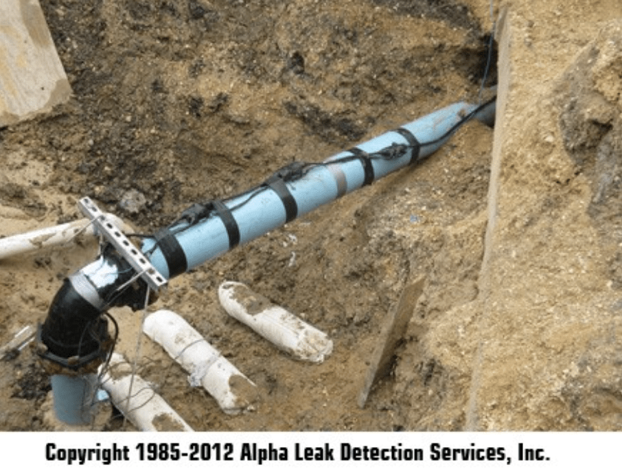
This is the first of two articles dealing with the CP design approach for buried pipelines. Cathodic protection (CP) is applied to prevent corrosion on buried pipelines in a variety of environments. Based on pipeline characteristics and environmental factors, CP design must be based on the specific project and site conditions. There are two types of CP systems, sacrificial or galvanic (SCP) or impressed current (ICCP), which are applied in many ways to provide CP on buried pipelines. The anodes in either type of system can be either distributed or remote, and in an ICCP system, the remote anodes can be shallow or deep. There are many different types and sizes of anodes for either type of CP system that can be installed either horizontally or vertically.
Optimizing Cathodic Protection Design
There are fundamental procedures that should be followed in each case, and the method of application of CP to a pipeline depends upon unique design considerations. Two main design factors, which are considered together and can generally indicate the type of protection recommended, are soil resistivity and pipeline coating quality. For buried pipelines, poor or lack of protective coating and/or high soil resistivity can virtually eliminate the practical application of SCP systems in many specific applications.
The first step in the design process is to collect and evaluate pertinent data regarding the pipeline, its operational characteristics, and its environment.
For buried pipelines, typical data includes:
- construction specifications
- pipe material, diameter, and wall thickness
- pipe and joint coating type, thickness, and conductance
- temperature, conductivity, and operating pressure ranges inside of pipeline
- location of interconnections related to the piping
- electrical continuity of the pipeline
- AC power availability and road access to possible CP facilities
- location of pipe casings, mainline valves, stations (e.g., compressor, pumping, metering, etc.), and directionally drilled sections
Current Requirements and System Selection
The CP current requirement is the current required for adequate corrosion protection of the pipeline and is used to help determine the type of system and the size and quantity of anodes. In general, systems with small stable current requirements (0.5 A or less per 100 lineal feet of pipeline) are good options for sacrificial anode type systems. Pipelines with larger current requirements (1 A or more per 100 lineal feet of pipeline), or where the current requirements vary considerably with time, are usually a better option for impressed current systems. When adding CP to existing pipelines, ICCP is usually more cost effective, unless the pipeline surface area is small and well coated.
Calculating CP Current
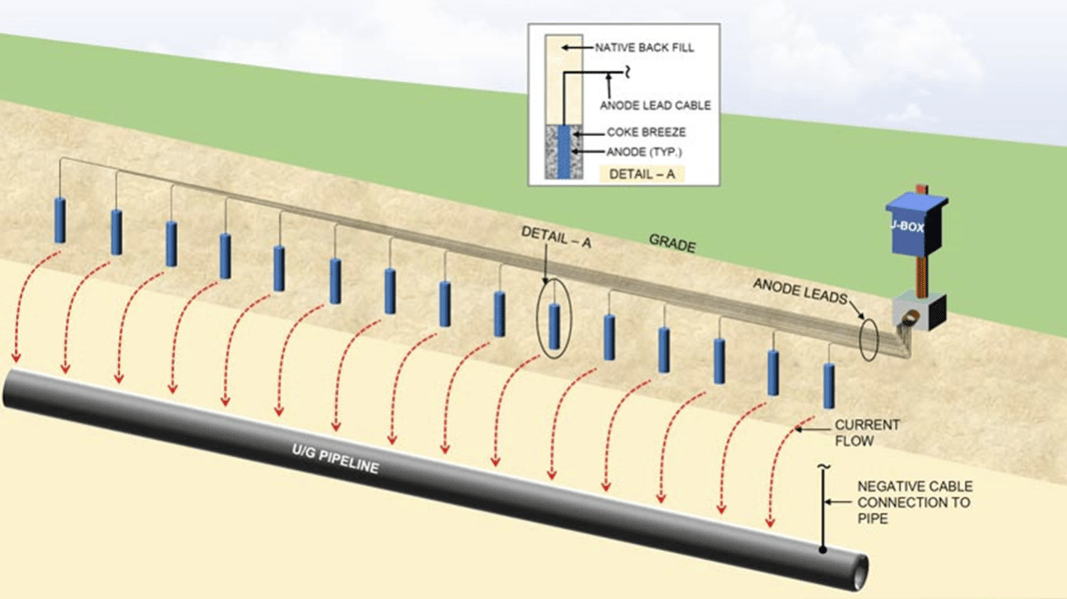
For CP design, the current requirement is based on the expected exposed surface area of the pipeline. Several factors affect the exposed area. The main factors are the pipeline surface area in contact with soil, properties of the protective coating, damage to coating during installation, percentage of surface coverage by the coating, and the current density required for CP in the environment. The expected current requirement depends on calculating the area of exposed metal in contact with the electrolyte and multiplying it by the “best estimate” of current density for the conditions present.
Selecting SCP vs. ICCP
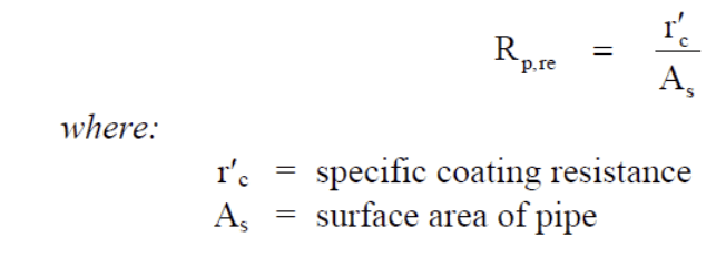
After the CP current requirements are determined the use of SCP or ICCP must be selected. Many factors affect this design choice, but the required current and soil resistivity are the predominant factors that impact the choice of which CP system to use. As the current and resistivity increase, ICCP becomes the best choice. Another key step is to determine the total circuit resistance of the CP system. This requires calculation of the anode-to-electrolyte resistance, resistance of lead wires and the pipeline-to-electrolyte resistance. The pipeline to remote earth resistance may be a factor if the pipeline surface area is very small or small with a good dielectric coating. For a coated pipeline, most of the resistance to remote earth will be across the coating. If a specific coating resistance is assumed, the resistance of the pipe to remote earth can be calculated from the following equation.
Anode-to-Electrolyte Resistance
In most ICCP systems, the major factor in the determination of total circuit resistance is the anode-to-electrolyte resistance. Anode and pipeline leads are normally sized so that lead wire resistance is often negligible. Lead wire resistance may be significant if long runs of wire are required, or anode-to-electrolyte resistance is very low. Calculating the Anode to Electrolyte Resistance, also known as “ground bed resistance” or “anode bed resistance,” is often the parameter that most impacts the CP system circuit resistance. Anode-to-electrolyte resistance depends on soil resistivity and the configuration, shape, and number of the anodes. The design approach starts by selecting the type, size, and shape of the anode to be used. Next, calculate the resistance of a single anode. Then determine the effect of the use of multiple anodes. The process is iterative, and several attempts may be necessary to determine the optimum anode system and corresponding anode-to-soil resistance.
The next article will cover system life, voltage calculations, and current distribution.
See how Technical Toolboxes’ AC Mitigation PowerTool can benefit your CP design approach as it’s a predictive maintenance software for pipeline corrosion.
More on Corrosion Information
For more information regarding this blog topic, read our Cathodic Protection Criteria and Current Requirements for Buried Pipelines blog or join us in a self-paced training on CP Circuits and Types of Corrosion. You can also contact me, the author, David Willoughby, at [email protected]
Suggested Post
The Trusted Tool Gas Engineers Didn’t Know They Were Missing
Do You Really Know What’s Flowing Through Your Pipes? The Trusted Tool Gas Engineers [...]
2026 API Compliance: What You Need to Know
2026 API Compliance: What You Need to Know By Kesley Price New rules. Tougher [...]
Corrosion Engineers: How Confident Are You in Your Remaining Strength Calculations?
Corrosion Engineers: How Confident Are You in Your Remaining Strength Calculations? By Kesley Price [...]


