CP Design Approach for Buried Pipelines; Article 2
David Willoughby
Introduction to CP Design Approach for Buried Pipelines
This is the second of two articles dealing with the cathodic protection (CP) design approach for buried pipelines. This article will cover system life, voltage calculations, and current distribution. The quantity of anodes required for the CP system depends on the current requirement and the maximum individual anode current output. As covered in the first article, the current requirement is a function of the pipeline size, coating, and environment in which it is installed. The maximum individual anode current output depends on the anode type, anode size, and environment resistivity. For sacrificial anodes, anode life is determined by anode current, anode type, and anode efficiency. For impressed current anodes, anode life is a direct result of current and time. Each anode has a specific weight loss per ampere-year calculated from Faraday’s Law or from manufacturer charts in anode life versus current discharge.
Factors Influencing Sacrificial Anode Life
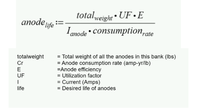
For sacrificial anodes such as zinc, magnesium and high purity magnesium, anode life is based on anode type, anode efficiency, effective useful life factor and anode current. The anode efficiency is a percent of the anode discharge for CP compared to the anode’s self-corrosion rate. Zinc is normally 90 percent, while magnesium and high potential magnesium is 50 percent. The effective useful life (utilization factor) is the percentage of weight loss before anode failure. For most anodes, failure will occur after 80 percent of the weight is lost.
Understanding Impressed Current Anode Life
In the case of impressed current anodes such as High Silicon Chromium Bearing Cast Iron (HSCBCI), the manufacturer or distributor for the anode will provide the anode consumption rate. HSCBCI is usually 1 pound per amp year. The effective useful life factor is usually 80 percent. In systems with multiple anodes, use the maximum anode output to calculate the life of the anode system (not the average anode output).
In the case of dimensionally stable impressed current anodes such as mixed metal oxide and platinized niobium, charts are available from the manufacturer or distributor for the specific anode, usually in years at specific current outputs.
![]()
Calculating Voltage for Sacrificial Systems
![]()
Calculating System Voltage for Sacrificial System: The initial driving voltage is the difference between the sacrificial anode open circuit potential and the pipeline corrosion potential. The intended operating driving voltage is substantially different from the initial driving voltage due to the amount of the original voltage used up in polarization at the anode and cathode.
For CP design purposes, the design driving voltage is the difference between the anode polarized potential and the chosen cathodic protection criterion. For example, if the chosen criterion is – 850 mV CSE and the polarized potential for a high potential magnesium anode is – 1700 mV CSE (50 mV allowance for polarization from an open circuit potential of -1750 mV CSE), then the driving voltage will be 1700mV – 850 mV = 850 mV.
Impressed Current CP Systems
Calculating System Voltage for Impressed Current CP System:

Applying Ohm’s law to an impressed system, which is a series circuit, the required power supply voltage is equal to the sum of the voltage drops (including polarization and back voltage) around the circuit as in the below equation. The semi-inert impressed current anodes have corrosion potential that are more positive than steel structures (graphite could be up to 1.0 V positive to steel). The term “back voltage” is used to account for anticipated anode and pipeline polarization plus the galvanic voltage difference. It is common practice to add an overvoltage compensation factor from 15 to 25% to account for deteriorating anodes.
Achieving Current Distribution in CP Design
Current distribution is a key factor in CP design. The amount of pipeline polarization depends on the current density applied across the electrolyte/pipeline interface. To maintain uniform CP at all locations on the pipeline requires uniform, or ideal, current density on all protected surfaces. However, ideal current distribution is virtually impossible to obtain in practice due to non-uniformity of the electrolyte, characteristics of the pipeline and placement of the CP anodes. The relative resistance of each current path in the CP circuit determines the current in that path and the resulting current density at the pipeline. The resistance of a current path is related to the path length (L), cross-sectional area (A), and material resistivity (p) according to the expression:

Pipeline Attenuation and CP Efficiency
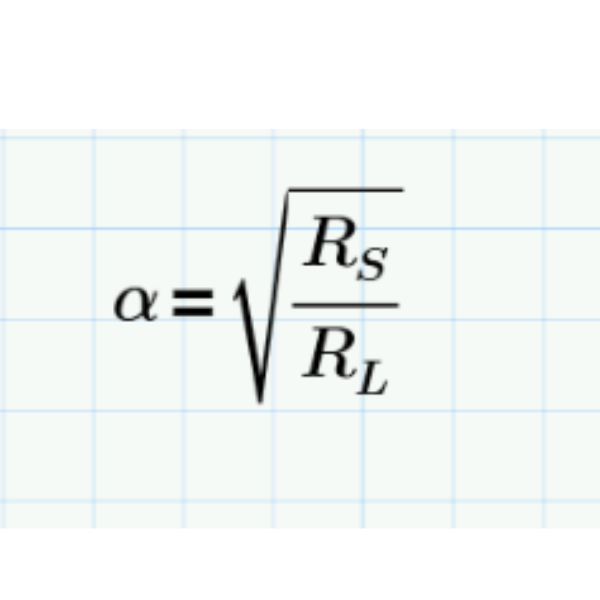
To complete the path for ideal current distribution, the current must enter the pipeline from remote earth. Under ideal current distribution, the magnitude of CP current in the pipeline increases linearly toward the drain point (the point of negative connection to the pipeline). On an electrically long structure, such as a pipeline, attenuation is the term applied to the decrease in pipe to soil potential shift produced by a CP system as the distance from the source of current, generally a rectifier, increases. On a pipeline, the incremental loss in pipe to soil potential shift is caused by an increasing current path resistance and diminishing current density. The voltage drop is greatest near the current source where the highest current flow is present on the pipe. The lower the attenuation, the greater the possible separation of CP power sources along a pipeline. The shape of the attenuation curve is governed by the relative values of the pipeline longitudinal resistance (Rs) in ohms per unit length and the pipeline leakage resistance to remote earth (RL) in ohms per unit length. These two parameters determine the pipeline attenuation constant that governs the rate of attenuation. The attenuation constant is related to the two pipeline resistance parameters as indicated in:

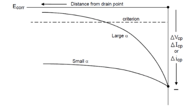
The attenuation constant controls the rate at which the current and voltage are reduced with distance from the drain point. A small attenuation constant results in a small amount of attenuation with distance, while a larger attenuation constant produces a much greater attenuation with distance from the drain point.
When Rs is large with respect to RL, the attenuation constant will be relatively large. When Rs is large with respect to RL, the attenuation constant will be relatively small. The attenuation constant will be large if, for example, the coating is poor, the resistivity of the environment is low, or the longitudinal resistance of the pipe is high.
Properly selected and applied protective coatings have a beneficial effect on current distribution and reduce the total current requirements. The principal effect of the coating involves its high electrical resistivity, which increases the pipeline leakage resistance thereby minimizing current attenuation.
More on Corrosion Information
For more information regarding this blog topic, read our Cathodic Protection Criteria and Current Requirements for Buried Pipelines blog or join us in a self-paced training on CP Circuits and Types of Corrosion. You can also contact me, the author, David Willoughby, at [email protected]
Suggested Post
The Network Modeling Tool Gas Engineers Didn’t Know They Needed
The Network Modeling Tool Gas Engineers Didn’t Know They Needed By Kesley Price You’ve outgrown your spreadsheets, now [...]
The Trusted Tool Gas Engineers Didn’t Know They Were Missing
Do You Really Know What’s Flowing Through Your Pipes? The Trusted Tool Gas Engineers [...]
2026 API Compliance: What You Need to Know
2026 API Compliance: What You Need to Know By Kesley Price New rules. Tougher [...]


