HDD Alignment & Borehole Geometry
By David Willoughby
Introduction
Let’s dive into the essential considerations behind selecting the optimal Horizontal Directional Drilling (HDD) crossing location – from alignment dynamics to constructability – and discover how these intricacies shape the success of HDD projects.
Pipeline Alignment and Method
The selection of the preferred HDD crossing location based on an overland pipeline routing assessment should consider the method of crossing, alignment, and access for the HDD construction. The pipeline routing should allow adequate space for pipeline layout areas, entry/exit pads, access routes, and minimal points of inflection in the design drill path and the pipe string layout area.
The selection of the HDD crossing location should be conducted in conjunction with the route selection to allow flexibility in using various crossing methods. This is especially important if the HDD fails and an alternative crossing technique or location is required. The HDD alignment should provide flexibility to use various accesses or vehicle crossing methods and flexibility in refining the crossing location if constraints prevent certain alignments.
The selection of a crossing method is an exercise in striking a balance among the previously discussed considerations to decide the most practical solution. The method that is preferred is usually that which is technically feasible and offers the required level of environmental protection for the lowest cost. Selection of an HDD crossing, when other methods are more cost-effective, technically feasible, and offer sufficient environmental protection, may be inappropriate. If an HDD is the preferred method by regulators and this method is considered to have a low likelihood of success or is otherwise impractical, the regulators should be provided detailed information on the crossing method selection process and the rationale for the rejection of the HDD method.
Navigating Terrain and Obstacles
The terrain and geometry of the location can have a significant impact on the borehole path and the feasibility of HDD. Construction problems can be expected if engineers and designers do not adequately consider the constructability of an HDD crossing. Too often HDD designs are an exercise in geometry without consideration of constructability. Every HDD includes crossing one or more obstacles. The HDD alignment and geometry should use the available entry and exit side space while meeting the requirements for clearance of the various obstacles, including set-back distances.
Considerations for Terrain and Obstacles:
- The relative location of the entry and exit points.
- The direction of the pilot hole, reaming, and pullback.
- Site’s surface, geotechnical, and topographical conditions.
When choosing the relative locations of the entry and exit points, remember that steering precision and drilling effectiveness are best close to the drilling rig. Where possible, the entry point should be located close to anticipated adverse subsurface conditions.
Borehole Path and Geometry in HDD Projects
The bore path line on the design plans represents the pilot hole. To maintain the required clearance distance from various obstacles the HDD design must consider product pipe and reamer diameter requirements. Consider the minimum horizontal and vertical clearance requirements when determining the HDD alignment including road setbacks, existing surface features, existing underground utilities, and other underground facilities. The HDD design must also consider the bore geometry for the ground profile. The bore geometry is influenced by the bore length and depth requirements, and the bending radius for the product pipe.
Penetration Angles:
- Entry angles are limited by equipment capabilities and should generally be designed between 8° and 20°. HDD rigs typically operate at 12° to 16°.
- Exit angles should be designed to provide ease in the breakover support of the pull section. Increased exit angles will require the pull section breakover bend to be supported at an elevated position during pullback. Exit angles generally range from 4° to 10°.
More on HDD
For more information regarding this blog topic, read our Product Pipelines Stress During HDD or join me in our HDD for Pipelines – Engineering Applications for Feasibility, Design and Stress Analysis (2-DAY) Training.
You can also contact me, the author, David Willoughby, at [email protected]

Suggested Post

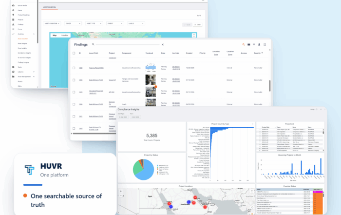
The Inspection Data Problem Is a Business Risk. Here’s What Operators Are Doing About It- with HUVR
The Inspection Data Problem Is a Business Risk. Here's What Operators Are Doing About [...]

Modern Gas System Modeling: Why Magnolia River Trusts GASWorkS to Keep the Pressure Up (Literally)
Modern Gas System Modeling: Why Magnolia River Trusts GASWorkS to Keep the Pressure Up [...]
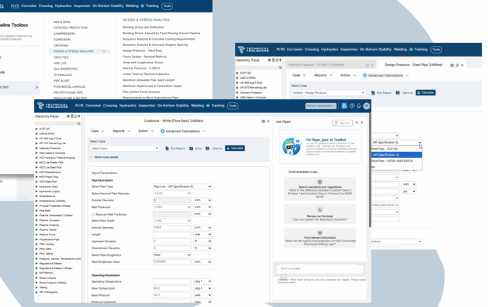
Engineering Calculations Built for Utility Pipeline Teams
Engineering Calculations Built for Utility Pipeline Teams By Kesley Price Pipeline engineers have relied [...]
Suggested Post
The Inspection Data Problem Is a Business Risk. Here’s What Operators Are Doing About It- with HUVR
The Inspection Data Problem Is a Business Risk. Here's What Operators Are Doing About [...]

Modern Gas System Modeling: Why Magnolia River Trusts GASWorkS to Keep the Pressure Up (Literally)
Modern Gas System Modeling: Why Magnolia River Trusts GASWorkS to Keep the Pressure Up [...]
Engineering Calculations Built for Utility Pipeline Teams
Engineering Calculations Built for Utility Pipeline Teams By Kesley Price Pipeline engineers have relied [...]