Product Pipelines Stress During HDD
By David Willoughby

Importance of HDD Design Process
Determining the loads and stresses that the product pipe will experience due to installation by HDD is not only an important process, but a primary concern for the owners and engineers of the product pipeline system as well. It is important that the owners and/or engineers ensure that the HDD contractor is provided with a crossing design that is acceptable for the product pipe.
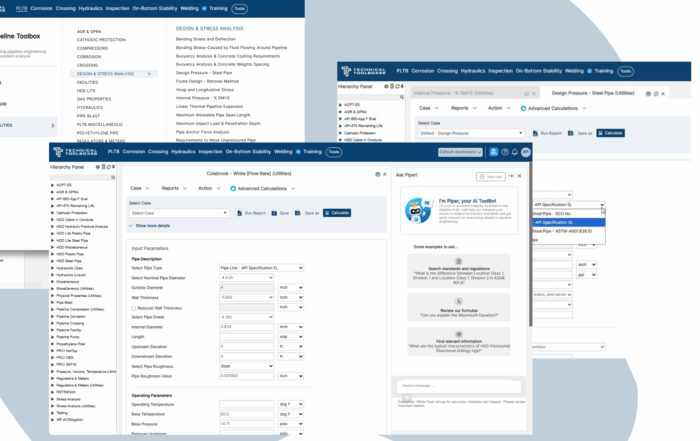
During the design process an evaluation, performed by software such as HDD Power Tool, of the product to be installed by HDD is critical. The design should evaluate the product pipes suitability for the installation loads, corrosion conditions, pull-in installation, and its intended function. In general, the pipe to be installed is limited to pipe that can be joined continuously, while maintaining enough strength to resist the high tensile stresses imposed during the pullback operation. Steel pipeline properties such as wall thickness and material grade, as well as the bore path profiles, must be specified so the pipeline can be installed and operated without risk of damage.
Calculating Product Pipe Pull Loads
Product pipe pull loads are calculated based on an analysis of the designed bore profile or the actual pilot hole. The entire bore path is made up of straight and/or curved sections and should include the fewest number of sections possible. However, the design can include as many sections as necessary to define the crossing. There are no boundaries on the length of any section. Straight sections may have a slight curvature if the pipe does not deviate beyond the walls of the borehole. Curved sections should be short enough to assume one constant radius for the entire sweep of that section. If the radius of curvature in a particular curved section is variable, break that curved length into small enough sections to justify the assumption of a constant radius of curvature in each smaller section.
Types of Stresses Encountered in HDD
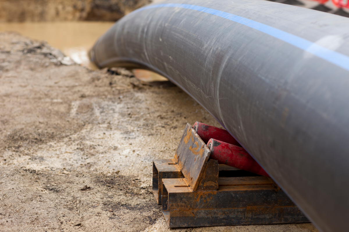
During HDD installation the pipeline is subjected to tension required to pull the pipe into the pilot hole and around curved sections in the hole. The tension comes from the frictional drag due to the friction between the pipe and borehole and the fluid drag caused by the pipe being pulled through the viscous drilling mud trapped in the annulus. In addition, tension results from the unbalanced gravity effects of pulling the pipe into and out of the borehole at different elevations.
The principal stresses of concern during the pre-installation stage are the hoop and longitudinal stresses caused by hydrostatic testing and the stress caused by the spanning distance between support rollers for the pipe. The distance between the support rollers is the free spanning distance and is used to calculate the maximum bending moments and the allowable span distance. If hydrostatic testing the pipeline, the pipe will be full of water and the additional weight of water must be included in the bending stress calculations.
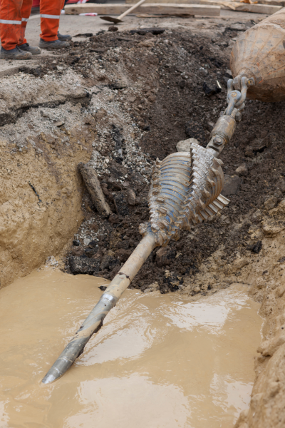
During installation, the spanning stresses mentioned above must also be considered. In addition, the theoretical pulling force on the product pipe must be determined to calculate the stresses that the pipe will see during the installation. A downhole friction factor is used to include the effect of the pipeline being pulled around a curve. The maximum predicted pulling force is then used in calculating the resulting longitudinal stress.
Operating Stresses of Concern
The operating stresses of concern include a combination of the longitudinal curvature stresses, external pressure stresses, and hoop and longitudinal stresses mentioned above. For operating stresses, the maximum working pressure of the pipeline is used to calculate the longitudinal and hoop stresses that will be imposed during service.
The worst stress condition for the pipe will be located where the highest combination of tensile, bending and/or hoop stresses occur simultaneously. In general, the highest stresses will be located at tight radius bending, high tension (closer to the rig side), and high hydrostatic head (deepest point).
Standards of Tolerable Stresses in the Industry
After determining the individual and combined stresses, they are compared with the allowable stress limits for the product pipe. There are many industry standards that address allowable stresses for various product pipe materials. For example, ASME B31.8 provides the following limits for natural gas pipelines (SMYS is the Specified Minimum Yield Strength of the pipe material):
– Maximum allowable longitudinal stress: 80% SMYS.
– Maximum allowable hoop stress: 72% SMYS.
– Maximum allowable combined stress: 90% SMYS.
Conclusion
For more information regarding this blog topic, please join me in either of the following two webinars: Horizontal Directional Drilling for Pipelines Feasibility Workshop or Horizontal Directional Drilling for Pipelines Design Example and Stress Analysis Workshop Or contact me, the author, David Willoughby, at [email protected]

Suggested Post

The Inspection Data Problem Is a Business Risk. Here’s What Operators Are Doing About It- with HUVR
The Inspection Data Problem Is a Business Risk. Here's What Operators Are Doing About [...]

Modern Gas System Modeling: Why Magnolia River Trusts GASWorkS to Keep the Pressure Up (Literally)
Modern Gas System Modeling: Why Magnolia River Trusts GASWorkS to Keep the Pressure Up [...]
Engineering Calculations Built for Utility Pipeline Teams
Engineering Calculations Built for Utility Pipeline Teams By Kesley Price Pipeline engineers have relied [...]