AC Interference Mitigation
By David Willoughby

Introduction
When it comes to AC mitigation, various methods have been used, but many have been found to be ineffective, expensive, and even hazardous. Effective mitigation requires engineering calculations, specific to the voltage levels, soil condition, and other specifics for the network to be analyzed which are included in software such as AC Mitigation Power Tool. For example, gradient control matting is often installed for aboveground structures without any engineering effort to verify the performance. While any gradient matting will lower the touch voltages, they may not lower them enough to safe levels if not properly designed. Pipeline and personnel hazards due to electromagnetic coupling to buried pipelines can be mitigated by grounding the pipe using ground beds, distributed anodes, horizontal ground wires, and by installing ground mats at points of possible human contact. The most effective location for a grounding installation is at a point where the induced voltage is maximum. A good ground established at these locations will reduce the local voltage distribution. To be effective a ground should be established at each induced voltage peak.
Methods of AC Mitigation
Some AC mitigation techniques used to reduce the AC interference levels on buried and above-ground pipeline sections are as follows:
- Design of a joint pipeline/power line corridor for minimum electromagnetic coupling including optimum phase sequencing of power line conductors.
- Pipeline grounding methods.
- Use of screening conductors.
- Use of insulating devices.
- Use of pipeline extensions.
- Gradient control methods.
Grounding to Achieve Mitigation
Two fundamental approaches are available for mitigating pipeline induced voltages, both of which are commonly referred to as grounding.
The first approach, more accurately called gradient control, is based upon the principle that a metallic electrode connected to the pipeline will cause leakage of the induced current from the pipeline to remote earth. This leakage current raises the potential of the adjacent soil closer to that of the pipeline, thus reducing the touch potential hazard for personnel. An example of this mitigation approach is the placement of gradient control mats, which are electrically connected to the pipeline, around valves, and in some instances around test stations. The use of such a device does not truly “ground” the pipeline since the potential of the pipe steel is not significantly reduced with respect to remote earth.
The second approach is to connect a very low resistance element to the pipeline. This element effectively “grounds” the pipeline in that the potential of the pipe with respect to remote earth is reduced to zero in the ideal case. It is also possible to have one “grounding electrode” perform both functions, i.e., due to its low resistance reduce the voltage on the pipe steel with respect to remote earth; and because of the simultaneous current drainage raises the local soil potential relative to the pipe steel.

What Does AC Mitigation Achieve?
Mitigation systems are designed to achieve the following objectives:
- During worst case power line load conditions, touch voltages at all exposed structures, such as valves, metering stations, and pig launchers/receivers, must be sufficiently low to minimize shock hazards to operating personnel and the public.
- NACE Standard SP0177-2014 recommends a 15-volt touch voltage limit, based on the let-go current threshold for most men.
- During fault conditions, as for steady state conditions, touch and step voltages at all exposed structures must be sufficiently low to mitigate shock hazards.
- ANSI/IEEE Standard 80-2001 provides safety criteria based on the heart fibrillation current threshold, derived from empirical work performed by Dalziel and others.
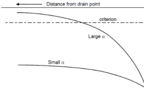
For a voltage peak to be electrically isolated so that its mitigation can be designed independently of the others requires a minimum physical separation between adjacent peaks. The peak voltage at one location must decay sufficiently so that it is small compared to the peak voltage induction caused by a physical or electrical discontinuity at another location along the pipeline. The required separation is determined by the propagation constant.
More on AC Mitigation
For more information regarding this blog topic, read our Digital Modeling of AC Interference on Buried Pipelines. You can also contact me, the author, David Willoughby, at [email protected]
Suggested Post
The API Inspector’s Digital Revolution
The API Inspector’s Digital Revolution: Maximize Field Time, Cut Report Delays, and Prove Return [...]
Intro to AI in Midstream: What’s Here, What’s Next, and What Still Needs You
Intro to AI in Midstream:What’s Here, What’s Next, and What Still Needs You By Marc Dungler AI [...]
Horizontal Directional Drilling (HDD): Designing for Success
Horizontal Directional Drilling (HDD): Designing for Success By David Willoughby Minimize Risk and Optimize [...]


