AC Interference Mitigation, Part II
By David Willoughby
Introduction
In Part 2 of the AC mitigation blog, we will expand on the grounding and gradient control addressed in Part 1. Understanding the relationship between pipeline mitigation characteristic impedance and grounding resistance is crucial for effective AC interference mitigation.
Importance of Grounding in Pipeline Mitigation
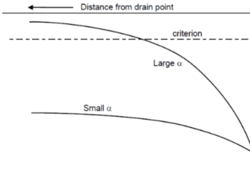
Grounding a pipeline near an isolated induced voltage peak reduces voltage. The effectiveness depends on the ratio of the pipeline’s characteristic impedance to the grounding resistance. A key point to remember is that grounding resistance should be at least 2 ohms lower than the pipeline mitigation characteristic impedance.
Note: Grounding resistances exceeding the pipeline characteristic impedance are ineffective for AC mitigation.
Designing AC Mitigation Grounding Systems
Proper design of AC mitigation grounding systems is essential to avoid a false sense of security and wasted funds.
Distributed Grounding Systems:
-
- Typically consists of vertically or horizontally installed grounding material like galvanic anodes.
- Connected to the pipeline at fixed intervals.
Spacing Considerations: The minimum separation between grounds should be 3-4 times the physical length to minimize mutual coupling. The maximum separation and overall length are determined by the required mitigation resistance.
Alternative Grounding Techniques
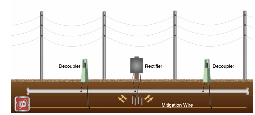
An alternative distributed grounding system is constructed by periodic bonding of the pipe to a continuous buried horizontal copper wire, or zinc ribbon installed parallel to the pipeline.
Whether one or two mitigation conductors are used, they require bonding to the pipeline at periodic intervals. To sustain a high level of effectiveness the distance between the pipe bonds should be the lesser of a small fraction, e.g., one-fourth or one-fifth of the pipeline propagation length or no more than twice the propagation length associated with the buried mitigation wire or ribbon.
Gradient Control for Voltage Reduction
When pipeline grounding methods are insufficient, gradient control methods are applied at above-ground facilities like test stations and block valves.
Gradient Control Principle: A metallic electrode connected to the pipeline causes leakage of induced current to remote earth. This raises the potential of adjacent soil closer to the pipeline’s potential, reducing touch potential hazards.
For example, if a powerline fault raises the pipeline potential to 5,000 V, the grounding mat also reaches 5,000 V, reducing the potential difference between the hands and feet of personnel.
Fault Current Mitigation
Mitigation characteristics for fault current inductive coupling are like those for steady state coupling since the coupling mechanisms are identical.
Discontinuities that give rise to pipe voltage peaks during steady-state operation also cause voltage peaks at the same locations when a power system fault occurs. In addition, each power line tower collocated with the pipeline is a possible discontinuity location. This is due to the flow of current towards the faulted tower from both directions resulting in dissimilar longitudinal electric fields along the pipeline on each side of the fault.
Continuous Mitigation: Since the fault location is variable, voltage mitigation at faulted towers, if potentially hazardous, may dictate the application of continuous and uninterrupted mitigation along the length of the affected region. During a fault condition, potential hazards exist for personnel and for the pipeline. Horizontal buried conductors not only provide a low grounding impedance at the point of connection but also act as gradient controls in the soil.
The conductors drain current from the pipeline, thus raising the potential of the local soil. The difference potential between the pipe steel and the local soil is reduced causing a reduction in the voltage across the coating, and likewise, in the touch potential.
Best Practices and Modern Strategies
As we have discussed, there are several methods for mitigating AC interference on buried pipelines. While gradient control wires are the most common form of AC mitigation, methods that combine the various types of grounding systems are also common.
Regardless of the pipeline grounding system used, the purpose and goal of any grounding system is to discharge the AC current from the pipeline. Be careful using old ideas, rules of thumb, and “we did it that way last time” mitigation designs. The mitigation design should be based on an assessment of the level of AC interference on a pipeline. AC mitigation is most effective when designed by experienced staff familiar with the AC mitigation strategies.
More on AC Mitigation
For more information regarding this blog topic, read our AC Interference Mitigation Part 1 blog or join me in our training on Pipeline AC Interference and Mitigation. You can also contact me, the author, David Willoughby, at [email protected]

Suggested Post

The Network Modeling Tool Gas Engineers Didn’t Know They Needed
The Network Modeling Tool Gas Engineers Didn’t Know They Needed By Kesley Price You’ve outgrown your spreadsheets, now [...]

The Trusted Tool Gas Engineers Didn’t Know They Were Missing
Do You Really Know What’s Flowing Through Your Pipes? The Trusted Tool Gas Engineers [...]
2026 API Compliance: What You Need to Know
2026 API Compliance: What You Need to Know By Kesley Price New rules. Tougher [...]
