AC Sectioning the Pipeline
By David Willoughby
Introduction
Collecting adequate powerline and pipeline data and sectioning the pipeline are key factors when performing alternating current (AC) interference studies on buried pipelines. Accurate information can prevent expensive installations and eliminate the incorrect positioning of AC mitigation systems. Computer modeling of the AC interference effects on buried pipelines has been in use for some time. The accuracy and reliability of the AC model depends on the data and proper sectioning of the pipeline.
While it has become an engineering best practice for the pipeline industry to model AC interference, inaccurate data, and improper sectioning can lead to considerable variances in the model data. Certain features, such as drains via direct or indirect bonds with other structures, actual pipeline coating resistance values vs model data, existing AC grounding, and soil resistivity data can affect the accuracy of the AC model.
Optimizing Modeling Accuracy
Dividing the pipeline and HVPL corridor into sections is a key part of the modeling process. This involves examining the physical placement of the pipelines(s) relative to the power line(s). This data is generally obtained from alignment sheets giving the collocation geometry along the right-of-way. The joint right-of-way is broken into a succession of pipeline sections. A new section is always defined whenever a physical or electrical change occurs along the right-of-way.
For example, if a pipeline parallels a power line at a fixed separation for some distance and then changes direction or the distance to power line changes, a new (pipeline) section must be identified. Any such changes are known as electrical discontinuities, and they create voltage peaks. Typical pipeline factors that affect sectionalization are pipeline diameter, pipeline coating, and soil resistivity.
Proper Pipeline Sectioning
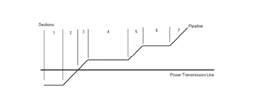
The section definitions shown in the figure are based on the change occurring in the physical distance or the angular orientation between the pipeline and the power transmission line. The figure shows the minimum number of sections that must be defined for the given right-of-way geometry. However, in general, if the length of a section that was defined based on geometry alone exceeds several miles, it is usually best to subdivide such a large length section into several smaller ones.
Advantages of Proper Sectioning:
- Higher resolution in the calculated pipeline voltage and current profiles.
- Accurate representation of field conditions.
When multiple pipelines are being modeled, each pipeline is individually sectioned discontinuities. If the AC model is not divided into proper sections, the model will not match actual field conditions.
For example, consider a pipeline where a new coating was installed on a repaired section of the pipeline. The new coating will have a higher resistance than the old coating. This will result in an AC voltage peak around the coating change. This peak would be measured in the field but would not be in the AC model unless the pipeline sectioning properly identifies the coating change. For your AC model to be accurate and identify the areas of peak AC voltage the sectioning must match the field conditions. Before you build the AC model, make sure that the sectioning reflects the field conditions.
More on AC Mitigation
For more information regarding this blog topic, read our AC Interference Mitigation blog or join me in our Cathodic Protection for Buried Pipelines Training. You can also contact me, the author, David Willoughby, at [email protected]

Suggested Post

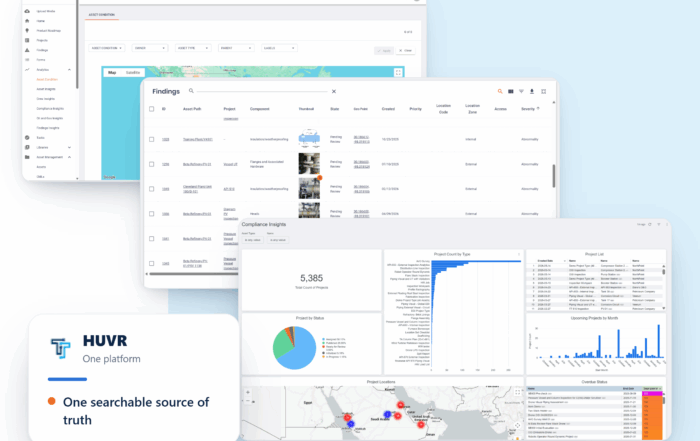
The Inspection Data Problem Is a Business Risk. Here’s What Operators Are Doing About It- with HUVR
The Inspection Data Problem Is a Business Risk. Here's What Operators Are Doing About [...]
Modern Gas System Modeling: Why Magnolia River Trusts GASWorkS to Keep the Pressure Up (Literally)
Modern Gas System Modeling: Why Magnolia River Trusts GASWorkS to Keep the Pressure Up [...]
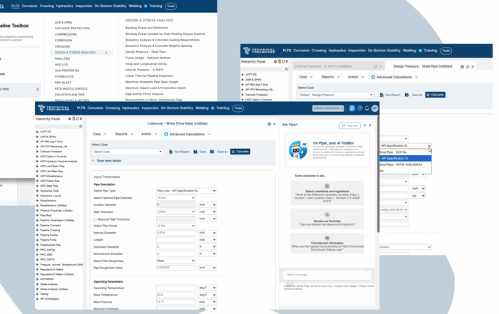
Engineering Calculations Built for Utility Pipeline Teams
Engineering Calculations Built for Utility Pipeline Teams By Kesley Price Pipeline engineers have relied [...]

Suggested Post
The Inspection Data Problem Is a Business Risk. Here’s What Operators Are Doing About It- with HUVR
The Inspection Data Problem Is a Business Risk. Here's What Operators Are Doing About [...]
Modern Gas System Modeling: Why Magnolia River Trusts GASWorkS to Keep the Pressure Up (Literally)
Modern Gas System Modeling: Why Magnolia River Trusts GASWorkS to Keep the Pressure Up [...]
Engineering Calculations Built for Utility Pipeline Teams
Engineering Calculations Built for Utility Pipeline Teams By Kesley Price Pipeline engineers have relied [...]