Factors Contributing to AC Interference
By David Willoughby
Introduction
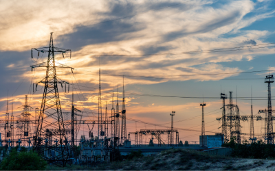
The problem of AC interference on pipelines and pipeline safety has gained in recognition due to increased current demand, improvements in pipeline coatings and the tendency for HVPL’s and pipelines to share rights-of-way. High Voltage Power Lines (HVPL) produce electromagnetic fields (EMF) that may result in interference on pipelines.
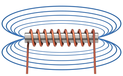
Electromagnetic fields (EMF)
The EMF induces an AC voltage onto the pipeline which creates AC currents. The magnitude of the AC current depends on many factors such as coating condition, soil resistivity, HVPL voltage, and separation distance.
Typically, each of the three phases on a HVPL carry approximately the same currents. Imbalances in the circuit can reduce the cancellation between the fields and increase the interference levels. Imbalances can also exist between the circuits in a multiple circuit HVPL and be caused by faults.
Longitudinal Electric Field (LEF)
The EMF produced by the powerline current generates an electric field running longitudinally along the pipeline known as the Longitudinal Electric Field (LEF). The LEF is measured in volts per length. The induced voltages on the pipeline are directly proportional to the LEF, which is directly proportional to the EMF, which is directly proportional to the HVPL phase currents.
- The EMF and LEF vary with distance from the HVPL and the phase wire arrangement on the tower.
- Pipelines experience minimal AC interference from bundled conductors because the separation for all three phases is basically the same, leading to the cancellation of the AC interference.
- Buried three-phase conductors parallel to a pipeline generally do not result in AC interference for the pipeline.
- The physical arrangement of multiple circuit HVPLs also impacts the LEF on the pipeline.
Impact of Soil Resistivity and Shield Wires
Soil resistivity and shield wires have a minimal secondary impact on the magnitude of the LEF. As soil resistivity increases, the LEF along the pipeline will show a slight increase. However, an increase in soil resistivity has a higher effect on the mitigation design than on the LEF. When a HVPL has shield wires, currents are induced in the shield wires from the phase wire EMF. As a result, the shield wires will have their own EMF that will oppose change in the HVPL EMF.
In other words, the EMF generated by the shield wire currents should lessen the overall EMF seen by the pipeline. This should also apply to currents that are generated in other paralleling structures, such as railway rails and foreign pipelines.
Factors that Impact AC Interference
The pipeline factors that impact AC interference are those that affect the electrical properties. These include pipe diameter, wall thickness, pipe burial depth, coating resistance, and coating thickness.
Coating resistance is the most subjective of the parameters in that field measurements of the resistance are generally unavailable.
In the case of a simple pipeline and HVPL corridor, where the LEF is uniform along the length of the pipeline, the location and magnitude of the voltage peaks can be calculated once the LEF has been determined. The voltage peaks appear at locations where the driving LEF changes in magnitude due to a physical discontinuity, e.g., a change in distance to the HVPL, or in phase because of a change occurring at a line transposition. Examples of peak voltage locations are locations where the pipeline either approaches or recedes from the ROW and joins a length of parallel section; locations where the separation between the HVPL and pipeline changes; power line transpositions; and pipeline crossings under the HVPL.
Voltage peaks also occur at places where the pipeline characteristics are changed. For example, where the pipe diameter or the coating conductivity changes. The ability to identify peak voltage locations by inspection greatly simplifies “worst case” calculations in that only these locations need to be considered.
Watch Our Webinar on AC Mitigation Strategies
For a more detailed discussion on AC mitigation strategies and practical solutions, you can watch my previously recorded webinar. This comprehensive session covers essential topics such as electrical interference in pipelines, grounding techniques, and best practices in AC mitigation planning.
Key Takeaways:
- Understanding electrical interference in pipelines and its impact
- Exploring effective grounding techniques for AC mitigation
- Strategies for AC mitigation planning to protect pipeline assets
- Insightful discussion on conductive interference effects and how to counter them
- In-depth analysis of AC interference risk assessment techniques
Watch the Webinar: Watch Now
Conclusion
For more information regarding this blog topic, check out our first blog on AC Mitigation called “Understanding AC power line to pipeline coupling mechanisms“, or join us on the training for Cathodic Protection for Buried Pipelines
Or contact the author, David Willoughby, at [email protected]


