Visual Indicators of AC Interference
By David Willoughby
AC Interference
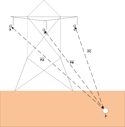
AC Interference introduces a series of issues into the operation of buried pipelines such as personnel safety issues, potential for AC corrosion, and potential for pipeline and coating damage. A pipeline which shares a common corridor with AC lines becomes energized by the magnetic and electric fields surrounding the power system in the air and soil. This AC interference can result in an electrical shock hazard for people touching the pipeline or metallic structures connected to the pipeline or simply standing nearby. Furthermore, damage to the pipeline’s coating, insulating flanges, rectifiers, or even direct damage to the pipeline’s wall itself can occur.
Factors
The magnetic field generated by the overhead power lines induces an AC voltage onto the pipeline, which creates AC currents. The magnitude of such currents depends on many factors such as coating condition, soil composition, power line currents, distance, etc. “Steady state conditions” designates normal operating conditions of the electric power transmission system, which can vary from low to high load conditions.
Conditions Results
AC interference levels during load conditions result from incomplete cancellation between phases due to the difference in the relative distance of each phase from the nearby pipelines and due to any unbalance in the currents the 3 phases carry. Although the longitudinal electric field may exist over the complete length of the pipeline exposure, voltages on the pipeline are generally induced at locations where the physical geometry between the power line(s) and the pipeline changes.
Examples of peak voltage locations include:
- Locations where the pipeline either approaches or recedes from the ROW and joins a length of parallel section.
- Locations where the separation between the two utilities changes.
- Power line transpositions.
- Pipeline crossings under the power line.
Changing Characteristics
Voltage peaks also occur at places where the pipeline characteristics are changed. For example, where the pipe diameter or the coating conductivity changes. The ability to identify peak voltage locations by inspection greatly simplifies “worst case” calculations in that only these locations need be considered. If the pipeline lies parallel to the conductors full coupling occurs. For perpendicular crossings of the power line, the coupling effect is reduced to zero.
Longitudinal Electric Field (LEF)
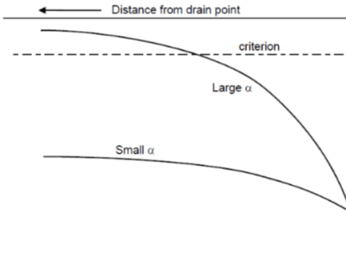
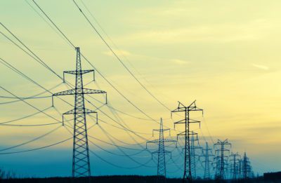
The electromagnetic field and the longitudinal electric field (LEF) vary inversely with distance from the HVPL. The LEF also varies based on how the powerlines are arranged on the tower. The separation between the phase conductors has a significant impact on the LEF as the LEF increases with increasing conductor separation. A pipeline will see only a portion of the magnetic fields in each of the phase conductors in inverse proportion to the separation between the conductors. The closest conductor (C) will have the largest impact on the LEF, and “A” will have the least impact. A larger separation between conductors results in less cancellation effects between their magnetic fields and a greater LEF on the pipeline.
For more information regarding this blog topic, check out our first blog on AC Mitigation called “Understanding AC power line to pipeline coupling mechanisms“, or join us on the training for: “Cathodic Protection for Buried Pipelines”
Or contact the author, David Willoughby, at [email protected]


