Digital Modeling of AC Interference on Buried Pipelines
By David Willoughby

Discovering the Right Tool
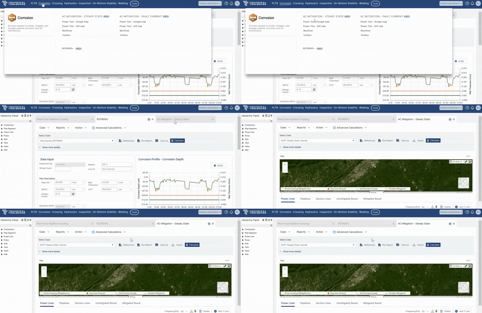
Using computer programs to predict AC voltage induced on pipelines requires the physical right-of-way (ROW) to be modeled. There is various software, for example, Technical Toolboxes AC Mitigation PowerTool, available for the digital modeling of AC interference on buried pipelines. These modeling tools are used to analyze the electrical effects of induced voltage on pipelines along with evaluating “what-if scenarios” during the design phase.
Though disagreements exist between the value of computer modeling and field analysis and design, both methods work if performed properly. Good field data is the key for both methods and requires system performance verification. A differentiating factor between the two methods is that the field designs do not cover fault conditions as they must be based on modeling.
AC Interference Modeling
AC interference modeling involves complex mathematical formulas to analyze the effects of induced voltage on pipelines caused by power lines operating under steady-state load conditions and during power system faults. These digital modeling tools are instrumental in displaying the complex conditions related to induced AC voltages. The selection of the proper modeling tool depends on what is needed for the analysis and the required output.
Performing AC Corrosion Analysis
The relative and angular positions of the pipeline, power lines, and other conductors in the area are numerically loaded into the AC interference modeling program. Other pertinent parameters, such as power line currents, pipeline diameter, pipeline coating resistance, and soil resistivity, are also loaded into the program. Depending on the sophistication of the software used for predictive analysis, one soil resistivity value may be input over the total length of the ROW, or variations in the soil resistivity along the ROW may be accommodated. Digital modeling allows the user to model and analyze the various conditions encountered in a collocated power line pipeline right of way.
Typical AC conditions modeled include:
- Steady state induced AC levels
- Pipe voltage potentials during phase-to-ground faults
- Voltage potentials to remote earth
- Step and touch voltage potentials
An important part of the AC modeling effort is identifying AC volts and calculating AC densities to assist with AC corrosion analysis. AC models are predominantly used to predict the levels and locations of AC interference on pipelines paralleling overhead power transmission lines. The primary method to determine AC density is to calculate the current density for a circular holiday by combining equations for resistance and surface area of the circular disk with Ohm’s Law.
Keeping to the Standards
Based on the AC model output and the mitigation approach, the modeler can select effective and economical AC mitigation measures. The goal is to ensure that the AC mitigation measures achieve the objective of NACE Standard SPO177 with a recommendation of a steady state 15-volt touch voltage limit. The model is also used to ensure that the AC mitigation measures achieve the objective of IEEE Standard 80 for tolerable touch and step voltages during fault conditions. This is the potential difference between two parts of the pipeline that can be contacted simultaneously and are at different potentials (e.g., the voltage difference across an insulating flange) or between the pipeline and the earth surface within reach of the exposed structure. During fault conditions, touch and step voltages at all exposed structures must be low enough to mitigate shock hazards. Mitigation measures also should ensure that during fault conditions, the coating stress voltages are sufficiently low to prevent arcing through coating holidays.
Conclusion
For more information regarding this blog topic, please join us in either of the following two webinars: “Cathodic Protection for Buried Pipelines” or “HDD for Pipelines – Engineering Applications for Feasibility, Design and Stress Analysis (2-DAY)”
Or contact the author, David Willoughby, at [email protected]
Suggested Post
The Network Modeling Tool Gas Engineers Didn’t Know They Needed
The Network Modeling Tool Gas Engineers Didn’t Know They Needed By Kesley Price You’ve outgrown your spreadsheets, now [...]
The Trusted Tool Gas Engineers Didn’t Know They Were Missing
Do You Really Know What’s Flowing Through Your Pipes? The Trusted Tool Gas Engineers [...]
2026 API Compliance: What You Need to Know
2026 API Compliance: What You Need to Know By Kesley Price New rules. Tougher [...]


