HDD Constructability Considerations
By David Willoughby
Introduction
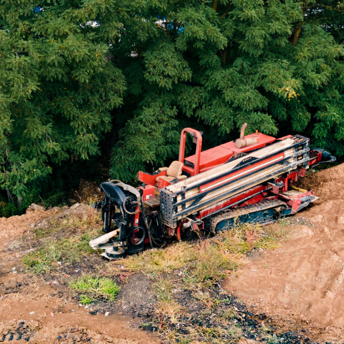
Horizontal Directional Drilling (HDD) is a specialized method of pipeline installation requiring specific contractor qualifications and specialized equipment. HDD’s range from relatively short crossings (less than 1,000-feet) to extremely long crossings (over 5,000-feet). As a result, the size of HDD rigs can vary substantially. The range of rig sizes and pullback lengths should be considered when considering the constructability of HDD. The capabilities of the rig should be assessed for each project. The assessment of rig capabilities should take into account the possibility that formations or other subsurface materials may be encountered that could cause difficulties with the HDD project.
Efficient Pipe Installation: Design and Execution
The pipe installation should be designed so that, wherever possible, the pipe string or drag section can be laid out and pulled back in one continuous section. The pipe will have to be lifted into place to match the exit angle of the drill to allow the drill rig to pull the section into place. The pipe string is usually placed on rollers as it is pulled into the drilled hole. The drag section may be cradled through a vertical curve to achieve the proper angle at the exit point. This curvature should be no more than the limiting curvature of the pipe.
Steering Technologies in Horizontal Drilling: A Comparison
It is necessary to ‘steer’ the drill head or mud motor during the drilling of the pilot hole. Several steering technologies are available. Two of the more common systems are known as the DigiTrak system and the TruTracker® system. The DigiTrak is a “walkover system” that is somewhat limited in the depth to which it is effective. The TruTracker® system is a “wireline steering tool system” and is utilized where the depth of the crossing is outside the range of the walkover system. Both systems provide effective steering.
Managing Buoyancy in Pipeline Installation: Strategies and Considerations
Uplift forces resulting from the buoyancy of larger diameter lines can be substantial. When a pipeline section is pulled through the bore, the buoyant weight of the pipe as well as the resulting drag forces between the pipe (pipe coatings) and the walls of the bore will act as resisting forces. High pulling forces may be required to overcome drag resulting from buoyancy uplift.
Buoyancy Control Strategies:
- Adding water to the pipeline section during the pullback phase, requiring an internal fill line to discharge water at the leading edge of the pull section (after the breakover point).
- Using a smaller diameter line inserted into the pull section and filling the smaller line with water to offset uplift forces.
The amount of water placed in the pipe is controlled to provide the most advantageous distribution of buoyant forces. Constant buoyancy may also be accomplished by these methods.
Comprehensive Monitoring and Reporting Protocols in HDD Crossings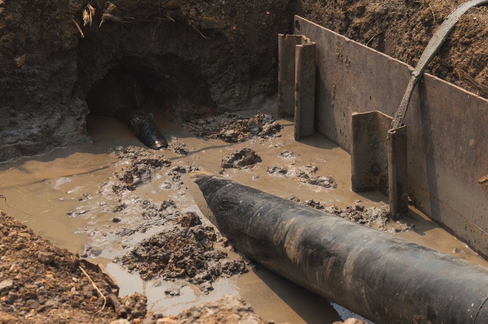
Monitoring and reporting are critical during an HDD since they provide a log of activities during the process to provide early identification of issues; make appropriate changes; provide a basis for mitigation; and provide a record of decisions and actions to demonstrate due diligence. It is important to ensure that sufficient records are maintained before, during, and after construction to support subsequent reports prepared to satisfy contractor, owner, or government reporting requirements. This should include detailed notes and photographs of all areas monitored.
Monitoring and Reporting Activities:
- Inspector daily records – a day-to-day account of the entire construction of the project.
- Contractor drilling records.
- Steering report.
- Drilling fluid volume balance report.
- Drilling fluid parameters.
- Drilling fluid additives list.
- Annular pressure modeling and reporting.
- Surface monitoring report.
- Pull force monitoring.
- Inadvertent return report.
Environmental Monitoring and Response Planning for HDD Projects
An environmental monitoring and response plan should be prepared by the contractor to address all the issues outlined in the permits. The drill path and surrounding area should be monitored up and downstream of the works. Where pressurized drilling fluids are used, monitoring should extend at a minimum 1,000 feet up and downstream of the crossing and be conducted on a fixed interval basis as identified in the permit. The exact distances will depend on the various issues at the site.
Monitoring should be documented and any evidence of fluid on the surface should be reported to the owner. If a loss of circulation occurs during the drilling program, the frequency of monitoring should increase to detect any inadvertent returns to the surface. Inadvertent returns occur when drilling fluids disperse into surrounding soils or randomly discharge to the surface. Such inadvertent returns are a result of the drilling fluid following the path of least resistance. To help prevent such releases the drill path should be aligned to avoid or minimize soils or formations prone to inadvertent returns. Conductor pipe (casing) at the entry hole may be installed and other drilling parameters established to maximize drilling fluid circulation and minimize the potential for unintentional drilling fluid returns.
Adding a stability checklist during constructability reviews helps teams verify downhole pressures, material properties, and contingency planning. The HDD Stability Checklist is a practical tool to improve constructability outcomes.
More on HDD
For more information regarding this blog topic, read our Product Pipelines Stress During HDD or join me in our HDD for Pipelines – Engineering Applications for Feasibility, Design and Stress Analysis (2-DAY) Training.
You can also contact me, the author, David Willoughby, at [email protected]

Suggested Post

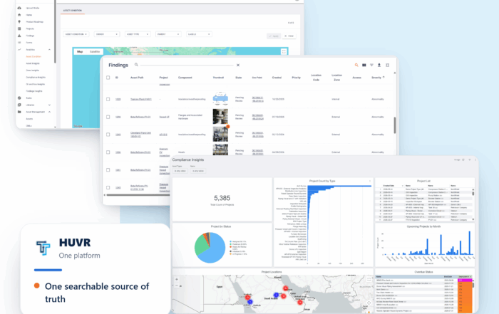
The Inspection Data Problem Is a Business Risk. Here’s What Operators Are Doing About It- with HUVR
The Inspection Data Problem Is a Business Risk. Here's What Operators Are Doing About [...]

Modern Gas System Modeling: Why Magnolia River Trusts GASWorkS to Keep the Pressure Up (Literally)
Modern Gas System Modeling: Why Magnolia River Trusts GASWorkS to Keep the Pressure Up [...]
Engineering Calculations Built for Utility Pipeline Teams
Engineering Calculations Built for Utility Pipeline Teams By Kesley Price Pipeline engineers have relied [...]
Suggested Post
The Inspection Data Problem Is a Business Risk. Here’s What Operators Are Doing About It- with HUVR
The Inspection Data Problem Is a Business Risk. Here's What Operators Are Doing About [...]

Modern Gas System Modeling: Why Magnolia River Trusts GASWorkS to Keep the Pressure Up (Literally)
Modern Gas System Modeling: Why Magnolia River Trusts GASWorkS to Keep the Pressure Up [...]
Engineering Calculations Built for Utility Pipeline Teams
Engineering Calculations Built for Utility Pipeline Teams By Kesley Price Pipeline engineers have relied [...]